I finished this bad boy 4 months ago and I am now finally getting around to the blog post. Hopefully this post is still a economically viable option considering how fast things like this come down in price. The unit has a very sharp image and runs over an hour off a small Li Ion battery. And yes, technically it's not HD, at 8.9" it's 1024x600, but it's a huge improvement regardless.
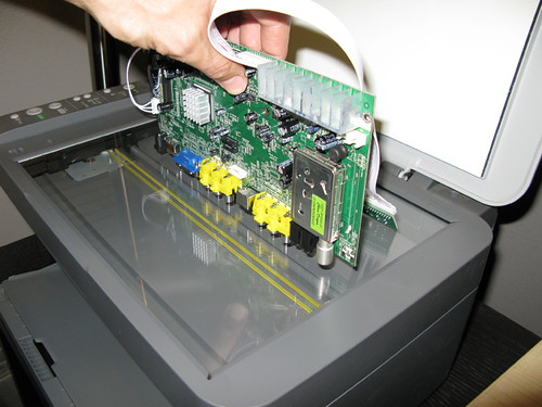
The story begins with my JVC GY-HM100u. I love this little camera, but it definitely has its quirks. One of its downsides is a tiny LCD screen. JVC could have bumped it up a tad even considering how small the camera is. The focus assist feature is however very nice and gives you sharp red highlights that indicate focus, but it still leaves me wanting more, especially in bright conditions. The LCD also lacks safe zones and horizon lines, so I was always shooting crooked. On top of all this, I'm getting into 35mm lens adapters using SLR lenses with manual focus only. This field monitor helps me see all my issues before they become problems.
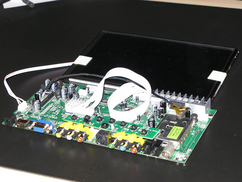
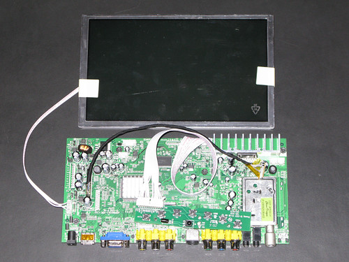
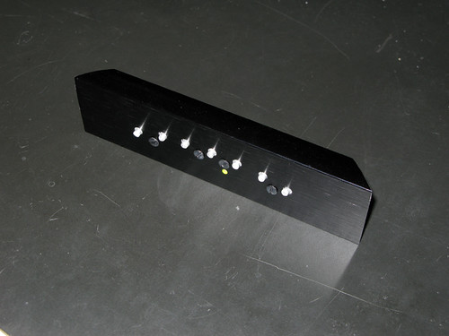
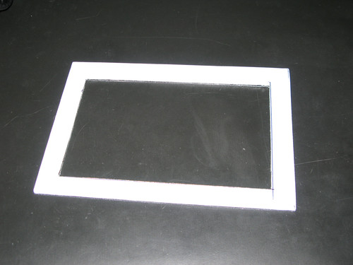
Once I had the screen components, I quickly noticed that the control board was wider than the screen itself. This meant the frame had to be ordered wider and I would have to frame the screen much like a mat on a picture frame. When I measured the board to order the frame, I went ahead and added 1/4" to my measurements just to be safe (and I'm glad I did). I went with a Black Metal SuperCanvas frame 9-1/2 x 6-1/4 x 1-3/4 frame from www.pictureframes.com ($17.20).
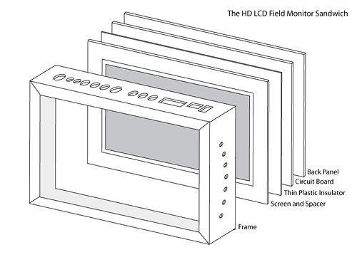
Once the frame arrived, I quickly tried putting all the pieces together to make sure everything was going to fit. Next, I drew up a diagram of how the parts come together.
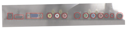
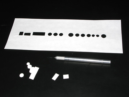
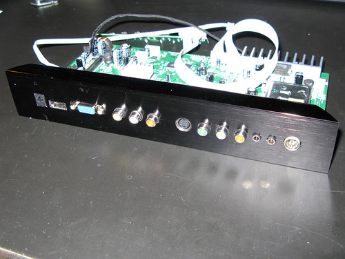
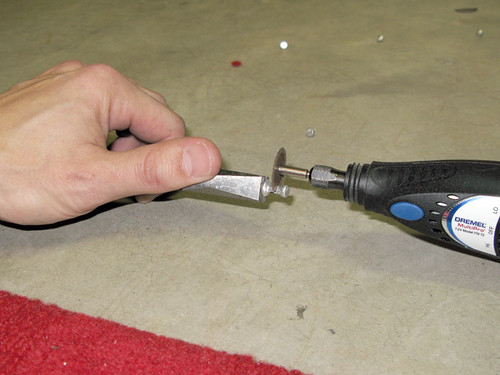
I printed my templates out and cut them out with an art blade, taped it to the frame and used a silver sharpie to transfer the shapes onto the frame. Using a drill press, I drilled out what I could and then used a dremel tool to clean up and shapes. After a lot of back and forth, my a/v connectors fit through the frame nicely. For the control buttons, I stumbled across a great solution here using modified push pins. I found some metal push pins and using the dremel tool, cutt off the ends and pins.
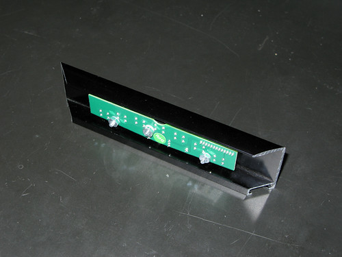
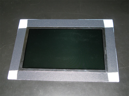
The next task up for grabs was the spacer or mat that I needed to put around the panel to compensate for the oversized circuit board. I could have made this out of wood, plastic, cardboard, etc. but I used this handy material called Alumilite I think. It's two thin sheets of aluminum with a pvc core. Alumilite is used as a printing material for high end signs. The last company I worked for had a lot of these old signs laying around so I'm putting them to good use once again. I measured the inside edges of the frame to get my outer dimensions of my mat, and measured the LCD panel to get the size of the opening I needed to cut. Here is the mat cut out and with the LCD panel installed. Used some good ol' gaffers tape to hold the panel in place.
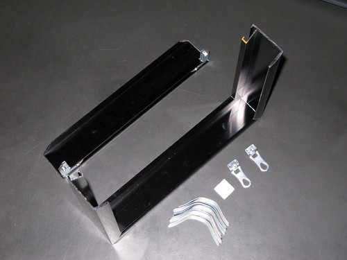
So with the unit all closed up, I now had to figure out how to mount this sucker to my camcorder. After searching around for parts and pieces to make something, I decided to cave and just buy a monitor arm. I went with the IKan MA101 ($69.99). I'm really glad I did too, the arm is built very well for being so reasonably priced. To attach the arm to the monitor, I used the little screw-ins that came with the picture frame. Normally you would put a wire across these to hang the picture, but I mounted a scrap piece of aluminum I had laying around with some nuts and bolts and drilled a hole in the center to attach the monitor arm. I used a wing nut here so I can easily mount and unmount in the field without the need for tools. I also added a few strips of velcro to the backside of the frame to attach the battery. The velcro holds pretty good, but I fear a good knock could send it flying.
Here is a shot of the panel in action. (Coming Soon!)
My camera dosen't have an image flip option (Unlike the HM700) so when I use the lens adapter I simply mount my LCD upside down! (Coming Soon!)
It only took me an additional 8 weeks to write this blog, and now I'm considering turning this into a vlog.